Showing posts with label Electrical. Show all posts

August 9, 2012

Finishing touches


We’ve finally reached the point during the trailer build where all of the major projects were done and there were just a handful of random small projects to finish up.  Instead of doing a bunch of short posts I thought it would be the easiest to lump them all in one before doing the FINAL reveal post.

Hooking up the trailer lights

When we bundled all of the wires together for the trailer into the liquid-tight connector that would be going into the tongue box, there were four wires that were still left exposed.  This was the wiring for the running lights on either side of the trailer (a hot and ground wire for each).  We had run these wires to poke out the front of the trailer, and then we ran them behind the front running board so that they would be grouped in the middle directly under the liquid-tight connector.


After adding some caulk to the hole in the running board that they were coming out of, we fed them into the bottom of the tongue box through a hole Darrell had to drill out. We used the same type of liquid-tight connector we used at the vent fan for the solar panel lights. Inside the tongue box they joined the wiring that goes back to the trailer hatch (for the brake, turn signals, and license plate lights). These wires then all leave the tongue box through the same bottom hole and then were attached to one half of a four pin connector.  This connector then hooks up to the trailer hitch when we are on the road so that the car can power and control the lights.


Tail light cover plates

We found some simple metal blank cover in the electrical section to hide the holes we made for the tail lights in the hatch.  These ended up being a great idea in the long run because now we had access to the tail lights in case anything electrical were to go wrong with them.


Hatch wiring.

I put some of the left over black loom over the wires running from the hatch to the pin connectors in the trailer.  This just cleaned up the look a bit and finished it off.


Sink plumbing

Our sink setup was really simple (though it looks kind of complicated.  We found a drain connection at Home Depot that fit our sink drain opening perfectly.  After cutting the length of the pipe to be a bit shorter, we then were able to adapt it to a garden hose connector with some PVC components, rubber hose and hose clamps.  Instead of buying a long length of garden hose, we were able to get a brass hose connector and clamp a shorter length of vinyl tubing to it. It looks bit wonky but works really well. 

For our water, we simply cut a length of clear vinyl tubing that would attach to the connection to the hand pump.  This tubing could then be fed into a re-used gallon milk jug we could fill with water.  Simple but effective!


The stove

Before fixing the stove to the pull out shelf, we decided to protect the wood from the heat of the stove and cooking goo with some more aluminum flashing.  It was cut to size and then nailed down along the sides of the shelf with twist nails.  This would also give us a surface we could easily clean and possible replace if needed in the future.

For the gas connection, Darrell was able to modify the regulator that came with the stove so that we could keep the propane hose connected at all times and still push the shelf in.  After this was screwed in and the stove located, we used some angle brackets to secure the stove in place.


Hatch pole

Though many people used hydraulic pistons (similar to what you might see on a car) we decided to go low tech and just use a long pole.  So that we could store it in the trailer, we bought two shorter wood dowels and then used a threaded insert and double sided bolt so that we could simply screw the two pieces together.  On the bottom end of the pole, we actually nailed on a rubber doorstop to provide the pole with a larger and more gripping foot.


On the hatch we used a wooden closet rod flange that I stained the same color as the counter for the pole to sit in.


J-molding above side doors

Above each of the side doors, we installed some curved j-molding.  This molding acts as a drip edge above the door to help protect it from rain dripping down the wall into the door.  We did our best to bend it to follow the curve of the door, but ended up making it a shallower curve.  It was difficult to bend and we didn’t want it to disfigure the shape as we were bending.  Since the curve was different, we decided to mount it about an inch above the edge of the door frame trim.


Weather stripping  

About the most frustrating part of the project was the weather stripping around the doors and hatch.  When everything was installed, the fact that ours was a home built trailer was definitely showing.  Though it looked great, there were some definite alignment issues at the doors and hatch, especially on the driver’s side door.  It was tight along the hinge and bottom of the door, but the top right corner splayed out almost a ¼”!  Also at the bottom of the hatch, it no longer was closing flush and we also had a pretty big gap to contend with.

Darrell finally, after a lot of research and hair pulling, found some ½” x ½” and 1” x 1” weather-resistant neoprene/EPDM/SBR foam that came in 25’ lengths.  This stuff was closed cell meaning that it restricts absorption and could be used outdoors.  It also had a super strong adhesive back that could be stuck to the T-molding around the doors. 

What we ended up doing was first taping the strips to the doors and through a series of measuring, opening/closing the doors and test runs, we trimmed down the weather stripping in the areas we needed to, while leaving other areas thick so that we could get custom seals around the doors.  After this was done, we crossed our fingers and removed the paper backing, permanently attaching weather stripping.  At the side doors, we also attached some thin rubber P-strip weather stripping (which we got at Home Depot) to the foam stripping for added sealing and protection.
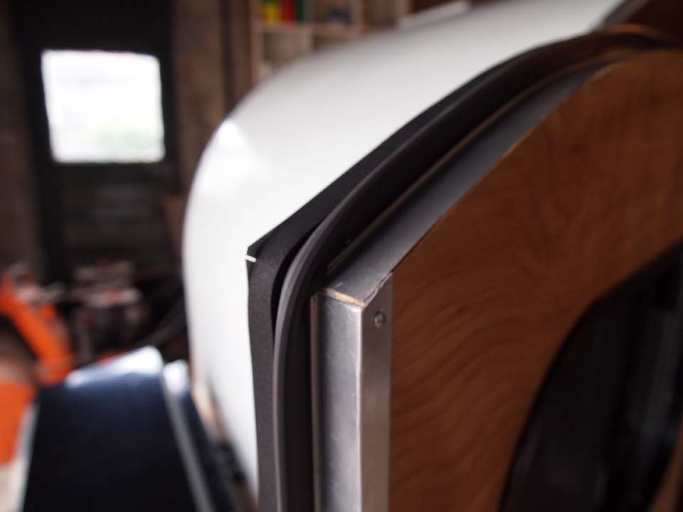


And after finishing the weather stripping… WE WERE DONE!!!  Some final photos and documentation of our maiden voyage to follow soon!

August 8, 2012

Final electrical & solar


With the paint finally dry (it took 3 days!) we were finally able to finish up the electrical.  First up was to install the vent fan.  There were two sets of wires that came out of the oak frame, red and white for the fan and black and white for the solar panels.  We first applied a ring of silicone putty at the very edge of the opening (Darrell found this at work and has no idea what it actually called) and then ran a heavy bead of caulk along the underside of the metal fan frame before positioning it on the roof.  We also put a dab of caulk at each screw hole before screwing it down.  Then all that was needed was to tie together the wires and install the white trim. 


After the fan was installed and the caulk mostly dried, we needed to drill a hole into the side of the aluminum so that we could run out the wires for the solar panels.  We then installed a liquid-tight connector to seal the hole.  We found this little guy in the electrical department at Home Depot.  The wires were then ran through the connector and into a black rubber tube that we fed into the connector as well.  This tube would then end underneath the nearest solar panel protecting the wires and giving us a water proof seal into the trailer. 


Next we were finally able to install the solar panels we purchased back in may.  Darrell was able to bend some metal angle clips we had used in other parts of the trailer to create simple brackets to attach the panels to the roof.  The panels had an aluminum frame around them already that he was able to screw the brackets to then, after some careful positioning, screw them directly to the roof, first filling the holes with caulk. After they were installed, he neatly trimmed the solar panel wires to length and connected all three together with a couple of caps and lots of electrical tape.


Back at the front of the trailer, we needed to install the second liquid-tight connector that would be attached to the tongue box.  With that done, the first of the cedar running boards needed to be attached since it would be difficult after the tongue box was installed.  Where the side walls and plywood skin met the metal trailer frame was really unfinished looking, plus the red frame was kind of ugly.  I decided the best way to cover the frame and finish off the trailer was to use cedar stock that could be attached directly to the side walls and skin.  The cedar would complement the darker okoume and wouldn’t need to be stained or treated with anything as it is a naturally weather and rot resistant material.


Next was installing the tongue box.  We decided to get a locking, weather tight box from Harbor Freight Tools, the same store we got the trailer frame from.  It was inexpensive but well built and we knew it would fit on the tongue perfectly.  Darrell first cut a hole in the back of the box where all of the wiring would come through. This eliminated the need for additional openings, thus preventing any leaks from occurring.  Of course this was where the liquid-tight connector fed through.


Within the tongue box we planned on housing the following components:
1)      Fuse panel
2)      Battery
3)      Solar charge controller
4)      Standard battery charger (120V kind)
5)      Spare components (Wheel bearings, chocks, etc.)
6)      Extension cord

The fuse panel was designed by my Dad and it consists of a volt meter, a 10Amp or 20Amp throw switch (depending on how much of a load we are going to be consuming) and a fuse block which has 12 inputs. We are only using 6 so that leaves room for a few for additional electrical items in the future if we want to add anything.  It also include a small has a small volt meter linked in so that when we push the red button under the LCD panel, it shows how much charge we have in the battery.


Each item within the trailer is wired to an individual fuse, this makes diagnosing any problems a breeze. The fuse box also is a terminal block which gives me the opportunity to only have to run one positive and one negative connection back to the battery.


Speaking of the battery, we opted for a larger marine deep cycle wet acid battery. This will give us the required capacity throughout the day that we would need without the worry of depleting the battery too much. The calculation is rather simple, you add together the amperage that you are going to be potentially consuming and multiply by the amount of hours that you will be using these amps.  In the electrical post, Darrell explained what we thought our potential Amps and Watt hours would be – it came to approximately 4.5 Amps.  We figured that we would not be using anything in the cabin during the day and would probably only be using the fan or charger or lights at night so max 15 or so hours.  Rounding up this gives us 70 Amp hour required.  The rule of thumb when selecting your battery is to basically double this capacity, thereby landing us at 140 Amps.  So we ended up buying the DC31 Sportman Marine Deep Cycle battery from our local marine store which has exactly a 140 Amp hour rating.  A bit overkill… maybe.  But we won’t have to worry about running out the battery in a single day.

In the electrical post Darrell also talked a bit about the solar charge controller.  The other thing that should be mentioned is that it also bypasses the fuse panel completely. Since we are dealing with such a small wattage on the solar panels you don’t really need to worry about any fuse needs. You connect the solar panels directly to the controller and then the controller directly to the battery.  We get around 14 volts in the direct sunlight which charges the battery over the course of a few hours quite nicely.  Typically the system will begin charging around 13 volts, and stop charging when it reaches 14.7.


One additional thing we did that is super convenient was to install a second volt meter in the cabin.  This is a smaller version of what is attached to the fuse panel, but works in the same way and is hard wired back to the fuse panel.  In this way, we can check on the battery levels while inside the cabin without having to get out, open the tongue box and all that.


Best of all, when all was said and done and everything was installed, the lights worked!!


June 7, 2012

Electrical Setup and Wiring

In the last post I worked out what our electrical usage would be based on the fixtures we would be installing and things we might be plugging in.  From this we determined we would be using two 20 watt solar panels that would be mounted on the trailer roof.  The electricity generated from the panels would then be 'stored' in a deep cycle marine battery which we still have to purchase - we just need to figure out which one. 

The power coming out of the battery is D/C current so we made sure that all of the fixtures (lights and fan) could run off of this without needing to be converted.  We also decided to keep things simple by installing 2 auxiliary ports in the trailer, one inside the sleeping quarters, the other in the galley.  These ports are the same type you would have in your car (the cigarette lighter type).  With these we can power most of our auxiliary equipment (e-reader, cell phone, laptop, etc.) with either a lighter plug or with a special inverter like this:

auxiliary inverter
installed auxiliary port in the galley

I also had to accommodate for the trailer running lights as well since they would be running off of the a plug attached to the car at the hitch.  What is nice about this is that there are numerous resources online to help you with trailer wiring.  There are also complete wiring kits for the brake lights you could purchase to make things even easier - ours came with the trailer frame we bought at Harbor Freight, so we saved the wires.  In a standard trailer like ours, we have 4 wires that run everything (break lights, turn signals, side marker lights, etc.), in our case these are Yellow, Brown, and Green.

I then decided on the color code of wiring to use throughout the rest of the trailer.  I decided to use red and white for all of the 12 Volt wiring as this is what I have seen in the past on cars and trucks. red would be the "hot/positive" and white would be the the "ground/negative".  All wiring is 16 gauge which is a bit overkill since the voltage and amperage on each item is so low, but I figured since we would never see the wires again after the roof was skinned, better safe than sorry.  I utilized about 200 ft of each color on the whole trailer since everything is running from each item back to where the fuse box will be in the tongue box (in both colors).  The last thing we wanted was another ground issue like we had with our first wiring job!

Simple Wiring Diagram

To feed all of the wires, I drilled holes on each side of the trailer through the center of each spar.  This acted as my wire chase to go to any place I would need within the trailer.  Normally I would have put these wires through the walls and on the underside of the trailer, but since we already buttoned up everything, this was the easiest method.  However, since we had yet to finish skinning the wall between the cabin and the galley, I was able to run wires for both auxiliary ports in this area by shaving away at the insulation to embed the wires.  That way they will be hidden when we finish the wall.

 
After all the wiring was installed, I checked the impedance of each wire group by connecting one end together (white to red) and testing the circuit with an ohm meter on the other.  This ensured that there were no tears in the shielding or breaks in the wire.  I should also mention that I labeled each wire group with the name of the fixture/outlet it was going to so we could keep track of everything - I cannot stress this step enough!!

note the explosion of wires

The galley hatch was a bit harder in the fact that we wanted to make it removable even after the trailer was completed.  To do this I added connectors at the hinge section so that we could literally 'unplug' the hatch before taking it off.  The wiring on the hatch was a bit easier in the fact that most of the were from the trailer wiring (break lights, license plate light, turn signals).  One thing I also did was to combine all of the ground wires from each light to a terminal block.  This meant that we would only need one white/ground wire back to the hitch connection.  The one item to tie back to the fuse box was the light for the galley.

running ground wires to the terminal block


While all this wiring was going on, we decided to install the lights we purchased for the cabin.  We located and installed these, pulling the two wires through the wall and attached them to the wiring I had already run.


Getting all the wiring done took a lot of prep work and thinking though, but will definitely make the trailer a more comfortable home for our travels.  Now we just need to get the fuse box and solar panels figured out!

May 23, 2012

Electrical Calculations and Design

Throughout this whole trailer build, we always wanted to build this thing "off the grid."  In other words, we wanted to have some of the conveniences of the world (lights/plugs/chargers/etc.) but didn't want to have to plug in anywhere.  So with some research we decided that solar would be the way to go.

The design of this system is actually quite easy.  Utilizing solar panels you "trickle charge" your battery as it is depleted and can do this with a solar charge controller.  What the controller does is it charges the battery and then cuts off the solar power when the battery is fully charged.  Think of it as a computer for your battery - it's "smart!"

Before purchasing anything, I first had to determine exactly what we would be powering so we would know what wattage of solar array we would need.  This meant we had to research and decide on all of the fixtures we wanted for the trailer so we could input their wattages into our calculations.  GAH!  After we gathered all the info I used the following method to calculate our potential electric consumption:


This is consumption over a period of 1 weeks time (typical method of calculating solar capacity)

To determine watt hours = (Watts x hours per day use) / 5 hrs [5 is the typical peak charging time available during a normal sunny day.]

Devices and Data 
12VDC Light (cabin)   10Watts     0.83Amps     6hrs/day use     = 12Watt hours
12VDC Light (cabin)   10Watts     0.83Amps     6hrs/day use     = 12Watt hours
12VDC Galley Light    10Watts     0.83Amps     6hrs/day use     = 12Watt hours
12VDC Fan (cabin)     20Watts     0.5Amps      6hrs/day use      = 24Watt hours
Laptop (AC voltage)    180Watts   1.5Amps      5hrs/day use      = 180Watt hours

Total = 240Watt hours / Day
Total = 1680Watt hours / Week

If we work through and determine what wattage of solar array we need we utilize the same technique, we finally decided on two 20 watt solar panels which we got from Northern Arizona Wind & Sun.

40 watts x 7 days per week x 5 hours per day of charging time = 1400 watt hours/week

Even though these numbers don’t match (1400 watt hours vs. 1680 watt hours needed) we decided that it would suffice, not only based on the cost of the panels but also on the sizes.  We only had a certain amount of space on the roof for the panels and any panels we found with a higher wattage output were too large.  This will just mean we have to be a little more careful with how much electricity we use and "rough it" a bit more.

Whew!  I know that was a lot of math (and a lot of words) but it gives you an idea of how to calculate out the size of a potential solar array on any of your future projects!  And because posts without pictures are boring, here is a photo of me in the midst of wiring which I will go into on the next post!